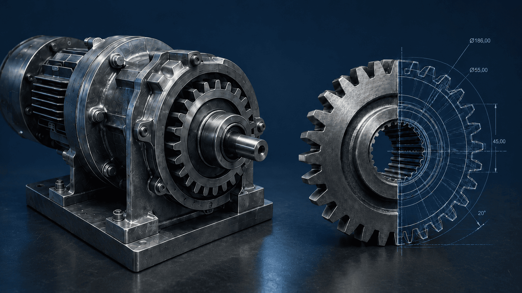
When a gearbox unit on an industrial line in Serbia stopped due to emergency wear of its drive gear, the equipment manufacturer — a European company from the late 1970s — no longer existed, and no drawings of the part had survived with either the operator or its service partners. The only way to restore the unit was reverse engineering: rebuilding the part from a physical sample, without a single page of original documentation. That is exactly how Rotors Tech, an engineering company working on similar cases across industrial sites in Europe, the Balkans, and Central Asia, approached the task — not a rough substitute “by eye,” but a full reverse-engineering cycle with 3D scanning, defect assessment, and quality control at every stage.
Why a Worn Part Cannot Simply Be Copied
The obvious approach — measure the worn gear and produce an identical copy — is also the wrong one. A part that has operated under load for decades no longer carries its original geometry; it carries the history of its own deterioration. Copying it directly transfers every defect into the new part and shortens its service life before it even goes into operation.
During inspection, engineers recorded a typical wear pattern for a part of this age and load history:
- wear on mounting surfaces;
- deformation in the working zones of the gear rim;
- fatigue cracks and micro-damage;
- erosion and corrosion on the metal surface;
- damage to keyways and threaded connections;
- loss of tooth-profile symmetry relative to the original form.
The goal of reverse engineering is not to reproduce this damage, but to reconstruct the part’s original, undamaged geometry — the form it had before it ever went into service.
How Reverse Engineering Works: From Measurement to 3D Scanning
Rebuilding technical documentation from a physical sample follows a proven sequence of stages:
- Measuring the part’s actual dimensions in its current, worn condition.
- Defect assessment — recording zones of wear, deformation, and damage.
- Material analysis: identifying alloy grade and hardness when this data is missing from any documentation.
- Identifying undamaged reference surfaces that retained the original geometry and can serve as a baseline for reconstruction.
- Geometry reconstruction — rebuilding the part’s original form from undamaged zones and the engineering logic of the assembly.
- Preparing technical documentation: drawings for future manufacturing.
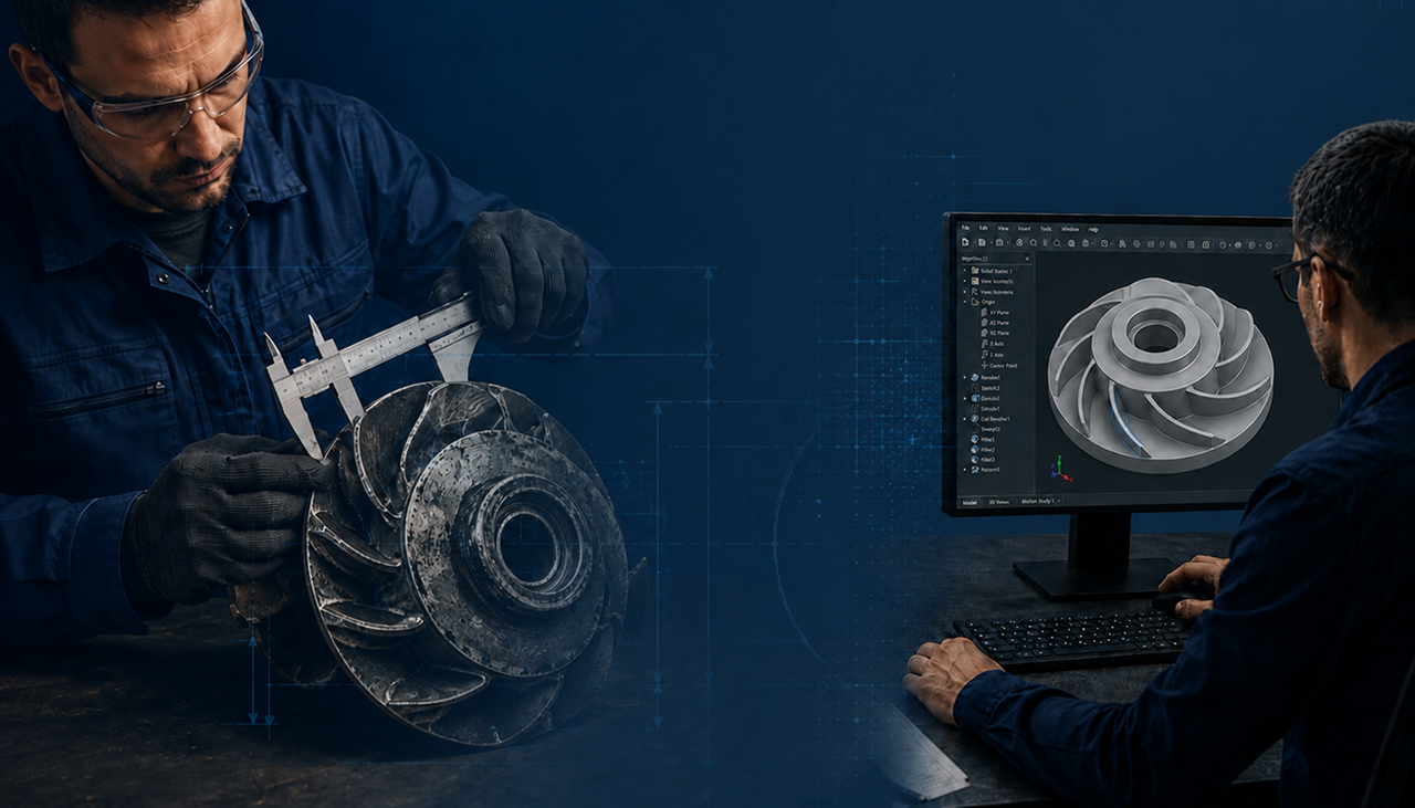
For the Serbian drive gear, measurement began with an on-site inspection: engineers recorded shaft dimensions and center distance and analyzed the wear pattern. Next came 3D optical scanning on Creaform equipment, capturing the part’s actual geometry with a precision manual measurement cannot achieve — the basis for the CAD model and tooth-profile reconstruction.
Restored Gear Parameters
| Parameter | Value |
| Module (m) | 20 |
| Number of teeth (z) | 19 |
| Pressure angle | 20° |
| Material | alloyed structural steel rated for shock and heavy-duty loads |
While building the CAD model, engineers found that the actual dimensions required adjustment relative to the initial measurements — the result of previous repairs and operational modifications made to the assembly over decades of service. This is a common situation in reverse engineering parts of this age: the engineering logic of the design matters more than a literal repeat of current, already-distorted dimensions.
Manufacturing and Quality Control
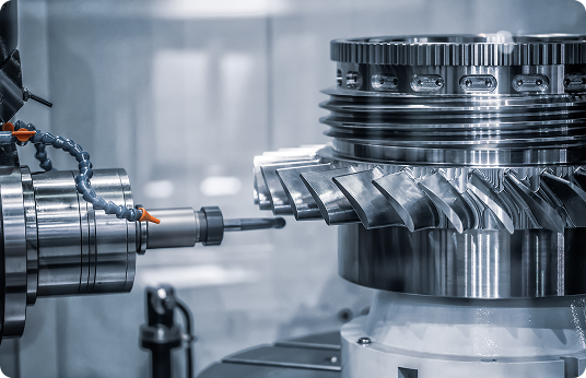
Once the digital model was approved, the part went through a full production cycle: turning, gear cutting, heat treatment to reach the required hardness and impact toughness, finishing, and quality control of the finished geometry against the CAD model. The customer received not only the physical part but an updated set of technical documentation and a digital model — so if this gear wears again, reverse engineering the assembly a second time won’t be necessary.
Result: The Line Returned to Operation Without Reducer Modernization
The restored drive gear installed into the assembly without modifying the reducer or replacing mating components — a risky and costly scenario that was avoided entirely. The line returned to operation without an extended shutdown, and the plant now has a part compatible with equipment from the late 1970s that no manufacturer has produced for decades.
Where Else Reverse Engineering Applies
The situation in Serbia is typical not only for drive units on industrial lines. Rotors Tech applies the same approach to components in turbine and power-generation equipment, where missing factory documentation is especially critical when planning major overhauls of thermal and combined-heat-and-power plants, as well as to parts used in metallurgical, petrochemical, and mining equipment — anywhere the original manufacturer has discontinued a part or exited the market, and downtime costs more than the engineering work needed to rebuild documentation.
For more on the restoration process itself, see How Rotors Tech Restores Worn Parts Without Factory Documentation. The full case description is available on the Reverse Engineering for an Industrial Facility in Serbia page. Learn more about the company on the Rotors Tech homepage.